1. Both piston and diaphragm pumps create pulsation or pressure peaks during operation, this being undesirable and detrimental to both the smooth operation and operational life of components. The fitting of an accumulator adjacent to down stream of the pump will dampen the pulsation to an acceptable level (fig.3). Typical applications are dosing pumps, pumps with a small number of pistons, etc.
2. In the case of a sudden power loss, e. g., pipe or joint failure, pump breakdown, etc., the accumulator can provide sufficient energy to complete an operational cycle or to allow actuators, valves, etc., to reset to a "safe" position, and so prevent damage to equipment or product. The availability of such an emergency power source is essential in cases where a hydraulic power supply is required for closing a safety door, electrical switch, safety valve, emergency brakes, etc.
A typical application is the emergency supply of fuel oil to power plant burners. Fig.4 illustrates that a failure at "B", causing a loss of energy, can be offset by manually overriding the electro valve "A", thus utilising the potential energy of the accumulator.
3. In a closed hydraulic circuit, thermal expansion can cause an increase in pressure due to a temperature rise.
An accumulator installed in the line will protect the valves, gaskets, pressure gauges etc. Common applications are found in refineries and pipelines(Fig.5)
4. As a constant static pressure is required for a long period, an accumulator is indispensable as it will compensate for pressure loss due to leakage through joints, seals, etc. as well as balancing pressure peaks which may occur during the operating cycle. Typical applications are found in closing systems (Fig.6), loading platforms, curing presses, machine tools, lubricating systems, etc
5. Rapid valve closure can produce shock waves(water hammer), resulting in overpressurisation of pipes, joints, valves etc. The use of a suitable accumulator can neutralise or significantly reduce the shock. Typical applications are water(Fig. 7), fuel and oil distribution circuits, washing equipment, etc.
6. Mechanical shocks in hydraulically driven equipment can be absorbed by accumulators. Possible applications are in drive and suspension systems for forklifts, mobile cranes, agricultural and civil engineering machinery, rock crushers, etc. (Fig.8)
7. Fluid separator(transfer barrier)
In a system where fluid pressure developed on one side of the circuit must be transferred to another fluid without any possibility of the two fluids intermixing, the bladder accumulator provides the satisfactory solution(Fig.9).
The accumulator bladder acts as a flexible barrier between the two fluids or between a gas and a fluid, providing an instantaneous response without reducing the system pressure.
Selesction
The following parameters are involved in the selection of an accumulator; the most important are.
1. Working pressure
The minimum and maximum working pressure (P1, P2), and the value of the maximum allowable working pressure must be lower or equal to the maximum authorised working pressure of the accumulator to be chosen for safety reasons.
2. Working volume
Volume(AV) of liquid to be stored or utilised is required in addition to the maximum and minimum working pressure for the correct sizing of the accumulator.
3. Working mediums
In general, the working mediums are nitrogen and hydraulic oil or emulsion. For special media, please consult us first.
4. Working temperature
The material selection of bladder and shell will be determined by the operating temperature, which also influences the pre-loading pressure, and consequently the accumulator volume.
5. Maximum flow rate
For the same (AV), the size of the accumulator connection can be influenced by the immediate flow rate necessary.
6. Location
It is important to know the eventual designation of the accumulator in order that the design can meet local design and test parameter.
7. Volume calculation
| Application |
Volume Calculation Formula |
Note |
| Fluid power storage |
V0=1−(P1/P2)1/nVx(P1/P0)1/n |
V0: Volume required (m3); Pre-charge pressure P0: 0.9P1>P0>0.25P2 |
| Vx: Efficient volume (m3) |
| P1: Min. operating pressure (Pa) |
| P2: Max. operating pressure (Pa) |
| n: Coefficient; n=1 (isothermal), n=1.4 (adiabatic) |
| Pulsation damper |
V0=1−(P1/P2)1/nAkL(P1/P0)1/n×103 |
A: Efficient area of cylinder (m2) |
| L: Length of piston stroke (m) |
| k: Coefficient related to pump type: |
| - Single-acting single piston: 0.60 |
| - Double-acting single piston: 0.25 |
| - Single-acting double piston: 0.25 |
| - Double-acting double piston: 0.15 |
| - Single-acting triple piston: 0.13 |
| - Double-acting triple piston: 0.05 |
| Pre-charge pressure: 60% of operating pressure |
| Absorb emergency energy |
V0=2mV2(P00.4)[(P2/P0)0.285−1103] |
m: General quality of hydraulic oil circuit (kg) |
| v: Fluid flow rate (m/s) |
| Pre-charge pressure: 90% of operating pressure |
Note:
1. Pre-charging pressure shall be determined according to application location.
2. n=1, in case compression or expansion of nitrogen takes place so slow(over 3 minutes) that a complete interchange of heat is allowed between gas and environment, that is at constant temperature, the condition is isothermal n=1.4, when operation is so quick that no interchange of heat can take place, the condition is adiabatic.
Model Designations

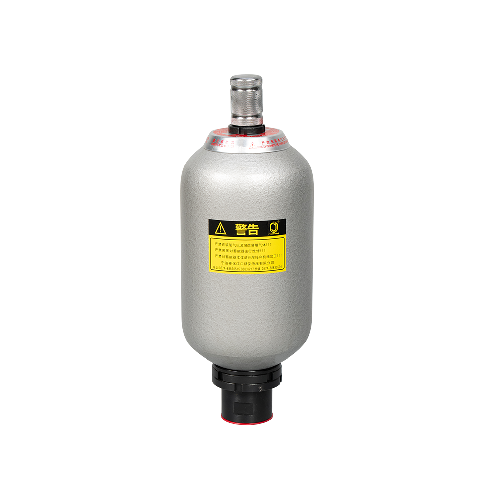
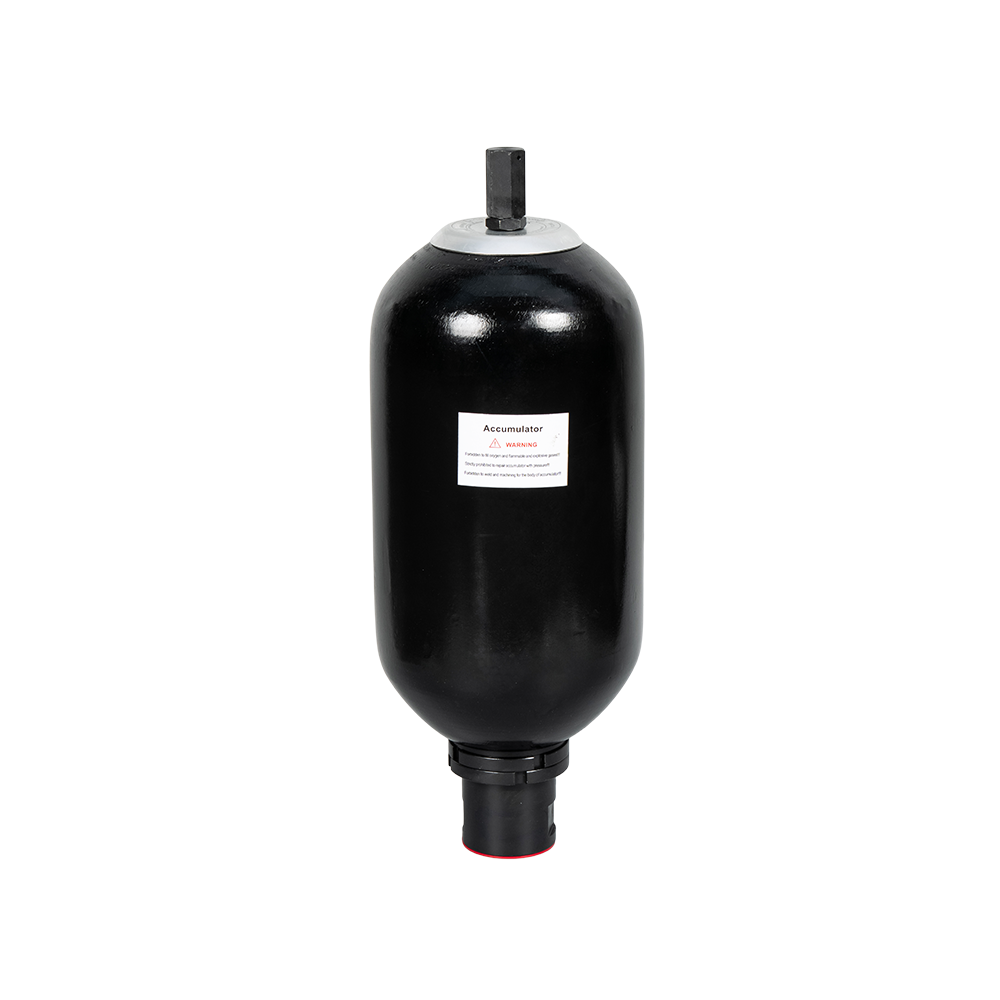
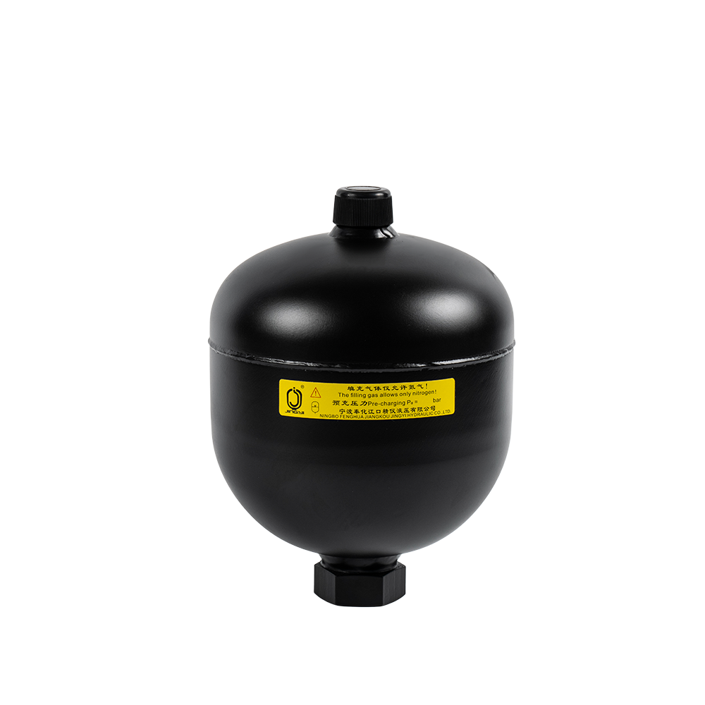
1. Hydraulic Bladder Accumulator
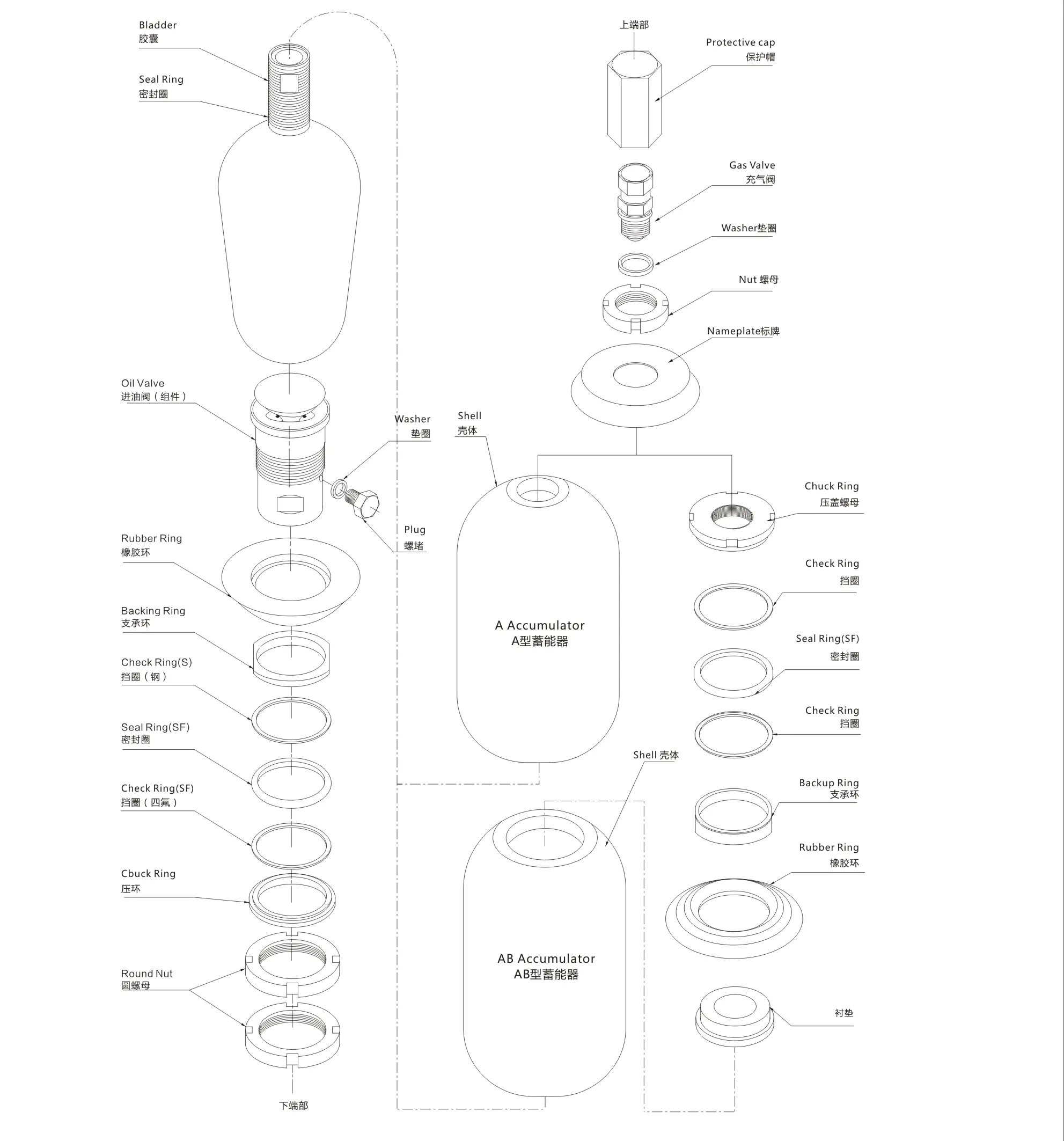
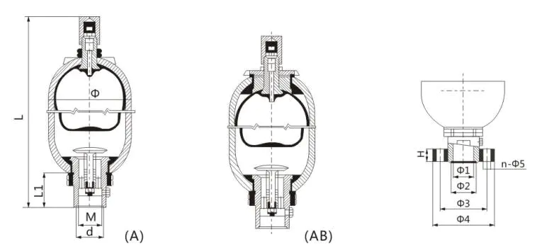
2. Structure: A: Small Opening AB: Big Opening
3. Nominal Capacity: L
4. Nominal Pressure: bar
5. Connection type: L--Thread F--Flanged
6. Medium: Y--hydraulic oil R--emulsion
Model Code and Size
Ordering Note
1. The model and the codes must be entirely indicated when ordering. For example, accumulator NXQ-A-40/31.5-L-Y means: working pressure:31.5Mpa, nominal volume: 40L, cylinder structure: small opening, bottom repair the medium: hydraulic oil, connection way: threaded, diameter: Φ219.
(1) Welding, reveting and mechanical machining are not applied to fix the accumulator.
(2) Oxygen or air is forbidden to fill the accumulator; only use nitrogen or other inert gas.
(3) When the accumulator is used to save energy, the filling pressure should be lower than 90% of the lowest working pressure of the hydraulic system (generally60%-80%)
(4) Check the connecting port for leaks when installing the accumulator.
(5) Check the pressure as required promptly after the accumulator is settled down.
2. When the user chooses the big diameter series accumulator of the same capacity, please note the diameter on the back of the model and code. For example, there are two kinds of pipes for a 40L accumulator, one is $219 and the other is $299, if the user need$299 diameter, working pressure: 31.5MPa, cylinder structure: big opening/top repair, medium: hydraulic oil, connection way: thread. this kind of accumulator should be expressed as following: NXQ-AB-40/31.5-L-Y(Φ299).
If the user choose a small diameter series, the diameter is not required to note.
3. If you have special requirements on the accumulator, please negotiate with the technical person of our company.
Installation
1. Accumulator shall be installed vertically with the gas valve upright. Inspection space shall be retained near gas valve.
2. Accumulator shall be fixed tightly on the supporter or wall.
3. When used for buffering and absorbing the fluctuation, accumulator shall be placed near the fluctuation source.
4. Check valve shall be placed between accumulator and hydraulic pump to prevent return flow of oil for the accumulator when the electric machine of pump stops working.
5. Stop valve shall be placed between accumulator and pipe system to be used in gas charging, draining speed adjusting or long term stopping.
6. Welding shall not be applied in fixing the accumulator.
Charging of Nitrogen
1. The accumulator shall be inspected before nitrogen is charged.
2. Nitrogen shall be charged slowly to ensure the bladder be not broken by quickly charging.
3. Oxygen, compact air or other flammable gas shall not be used.
4. The gas charging device shall be used in charging the Nitrogen. Gas charging device is inseparable part of accumulator to be used in charging, draining measuring and adjusting the charging pressure Gas Charging Device.
5. Determining of charging pressure:
(1) Buffering impact: Charging pressure shall be the normal pressure of installation site or a little above.
(2) Absorbing fluctuation: Charging pressure shall be 60% of average pressure of fluctuation.
(3) Storage of energy: Charging pressure shall be lower than 90% of minimum working pressure(generally60%-80%) and higher than25% of maximum working Pressure.
(4) Compensation for hot swelling: Charging pressure shall be the minimum pressure of close circuit of hydraulic system or a little lower
Inspection and repair
1. Inspection of leakage:
After installation, check the gas pressure in bladder every week.A month later, check every month, half a year later, check every half year.
Inspection method:
Place a check-valve in the oil pipe connects the accumulator oil-inlet and oil box, and installs a pressure gage before the check-valve. Open the check-valve slowly to let pressure oil return to oil box and watch the pressure gage simultaneously. The pointer of gage at first turn down slowly, turns dwon rapidly to zero at a certain point. The changed value of moving speed of pointer is the gas charging pressure. Besides, gas charging device could be used to inspect pressure, but gas will be discharged abit during each inspection.
2. When accumulator is not used for a long period, the check-valve shall be closed to ensure that the oil pressure is above that charging pressure.
3. If the accumulator does not take effect, check whether there is leakage. If there is no nitrogen in the bladder and oil is out of gas-valve, please check the bladder.
4. Drain the oil before demount accumulator.First let out the nitrogen with the charging device, then the parts can be demounted.
5. If there is leakage because of loosening of nuts in the process of transportation and testing, please check that seal ring is in the slot. Place the seal ring in the right place and revolve the nut. If leakage still exists, please change the parts.
Appendix
1. Before debugging, air in the pipe shall be expelled.
2. Place a safety-valve in the oil-inlet when accumulator is larger than 10 L.
3. Check the nitrogen pressure before the accumulator take effect.
4. Oxygen and flammable gas are prohibited in avoidance of explosion.
Bladder accumulator assembly schematic drawing